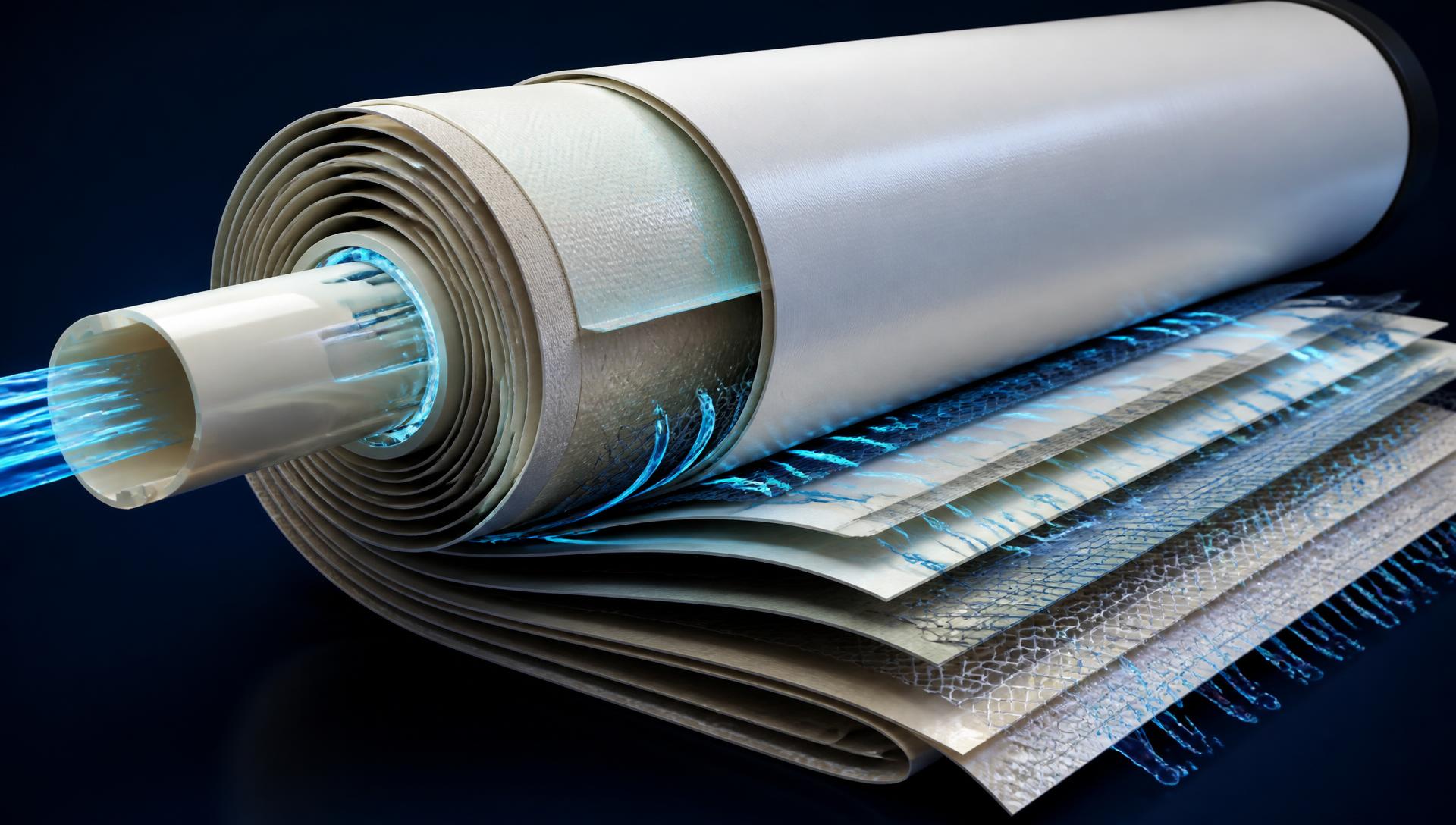
SV-NanoMatrix™ Technology Architecture
Engineered for stability. Built for long-term performance.
Thermo-engineered surface protection, precise selective layer control and HDG — Hydrodynamic Channel Geometrics deliver reliable, high-performance RO for the most demanding industrial wastewater applications.
Three sciences, one element
The SV-NanoMatrix™ architecture
Every membrane combines polymer science, surface science and hydraulic geometry — engineered together rather than optimized in isolation.
Thermo-FR™ Surface Shield
A thermally conditioned protective layer that controls adsorption and adhesion kinetics on the active surface.
Read the science →Selective Layer Architecture Control
Engineered polyamide network: crosslink density, chain packing stability and free-volume connectivity.
Read the science →HDG — Hydrodynamic Channel Geometrics
Symmetric open feed-channel architecture engineered for stable shear and predictable ΔP growth.
Read the science →Better Hydraulic Stability
Uniform flow distribution and lower pressure drop.
Superior Fouling Resistance
Reduced deposition and higher cleaning recovery.
Optimized Geometries
Minimized dead zones and hot spots.
Stable Long-Cycle Performance
Consistent operation and extended membrane life.
Higher Productivity
Better flux performance and predictable ΔP growth.
Engineered Precision
Science-driven precision for every operating condition.
Thermo-FR™ Surface Shield Technology
Advanced protective layer for superior anti-fouling performance
In wastewater RO, performance loss is driven by surface interaction thermodynamics and adhesion kinetics, not only by bulk fouling load. Fouling initiates with rapid adsorption of dissolved organics and biopolymers onto the polyamide interface, followed by anchoring and consolidation of colloids and biological precursors into a compact, highly bonded fouling matrix. That layer increases local mass-transfer resistance, intensifies concentration polarization and gradually alters near-surface hydrodynamics — producing normalized flux decline and unstable long-cycle performance.
The Thermo-FR™ Surface Shield is a functional protective layer engineered onto the active surface to control these interaction mechanisms. It is stabilized through a controlled thermal conditioning approach so surface behaviour stays durable under cyclic hydraulic loading and repeated cleaning exposure. By reducing foulant attachment strength and suppressing development of an irreversible bonded matrix, deposited matter remains less compact and more recoverable during flushing and CIP.
- Reduces foulant attachment and adhesion
- Suppresses irreversible matrix formation
- Improves cleaning recovery efficiency
- More stable long-cycle operation
Engineering outcome
Improved cleaning recovery efficiency, reduced irreversible fouling accumulation per cycle and more repeatable long-cycle operating stability.
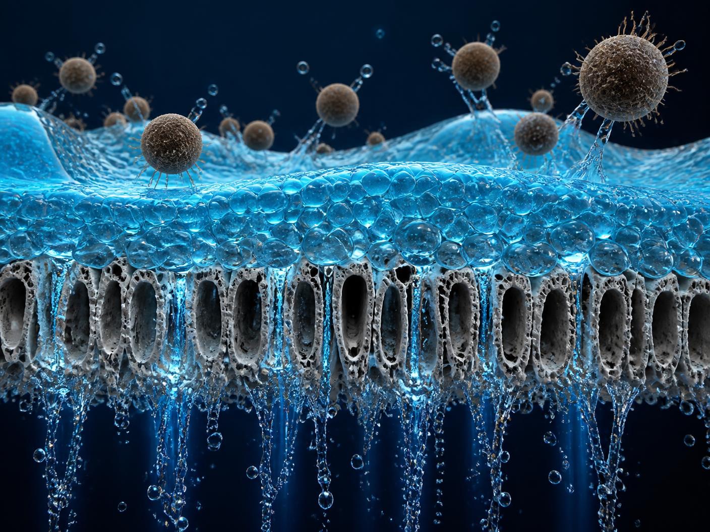
Fouling interaction control
Thermo-FR™ modifies fouling behaviour at each stage of the deposition sequence, reducing irreversible, bonded foulant buildup.
| Mechanism | Standard membrane | With Thermo-FR™ coating |
|---|---|---|
| Stage 1 — Interface contact | Rapid adsorption of dissolved organics and biopolymers | Reduced adsorption on the conditioned surface |
| Stage 2 — Consolidation | Strong anchoring of colloids and biological precursors | Weak anchoring, limited matrix consolidation |
| Stage 3 — Deposit state | Compact, highly bonded foulant film | Loosely bound, easily removable deposit |
| Stage 4 — Recovery | Partial CIP recovery, rising baseline | High flushing/CIP recovery, repeatable baseline |
Selective Layer Architecture Control
Engineered for stable transport, high rejection and long-term integrity
The RO selective layer is an ultrathin polyamide network where permeation occurs through nanoscale transport pathways governed by polymer microstructure and free-volume distribution. Transport stability depends on maintaining uniform layer formation and consistent molecular packing so diffusion pathways remain stable over extended runtime. In industrial RO operation the selective layer experiences continuous hydraulic compression, chemical exposure and dynamic loading, which can alter effective transport behaviour if microstructure uniformity is not controlled.
Molecular simulation confirms the mechanism: the engineered network raises fractional free volume compared with standard aromatic polyamide (TMC–MPD). Because these free-volume pores are accessible to water they act as diffusion pathways and explain the higher water permeance, while a flexible aliphatic ring regulates chain packing, reducing nanoscale defects and improving NaCl rejection.
- Uniform layer formation and consistent packing
- Controlled free-volume distribution
- High water permeance
- Excellent salt rejection and long-term stability
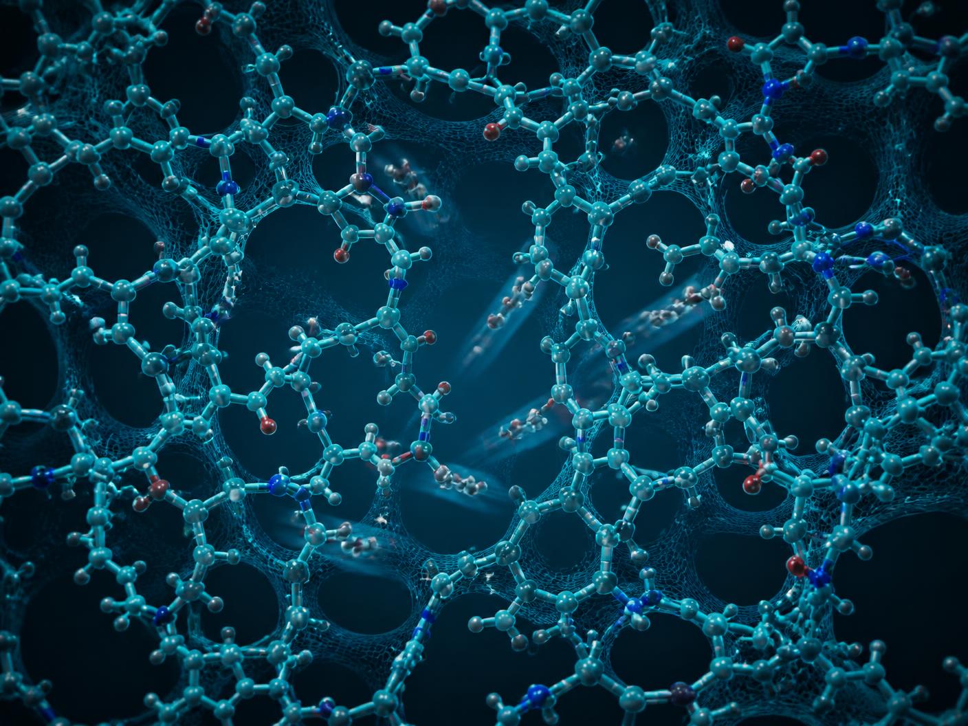
Fractional free volume (probe radius 1.4 Å)
Higher fractional free volume and greater polymer-chain mean square displacement (MSD) indicate more accessible water diffusion pathways at equivalent rejection.
Materialology
What we engineer at polymer level
Selective-layer performance is dictated by how the polyamide network is formed at nanoscale — its crosslink density, chain packing stability and free-volume connectivity. In wastewater RO, chemical exposure and mechanical compression gradually shift these transport pathways if the polymer matrix is not engineered for stability.
- Higher structural stability of the polyamide network under compression and chemical cycling
- Controlled free-volume connectivity for stable water transport pathways
- Lower long-term permeability drift without sacrificing separation integrity
- Stable transport response under operating stress — less drift with time
- Permeability–rejection balance retained during variable feed loading
- Repeatable performance behaviour across long operating cycles
Geometrics control
Selective layer geometry at micro/nano scale
Selective layer performance is not only chemistry — it is also geometry: thickness uniformity, surface micro-topography and structural consistency across the active area. Local non-uniformity creates micro-zones of higher flux or higher concentration polarization, leading to uneven loading and early localized fouling.
- Uniform active-area loading that reduces micro hot-spots of high flux
- Reduced localized concentration polarization through consistent transport behaviour
- Thickness uniformity and controlled surface micro-topography across the active area
- More stable long-cycle repeatability by minimizing local failure-initiation zones
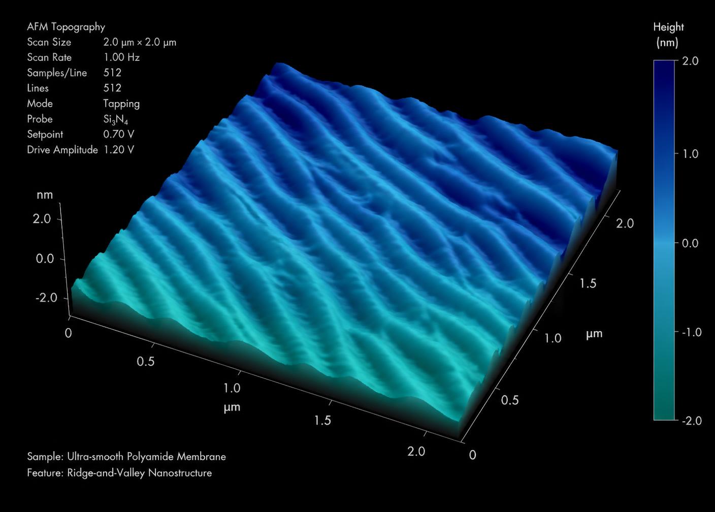
Surface roughness vs. modifier concentration
Concentration in aqueous phase (%) · Surface roughness (nm)
Excess micro-phase formation creates defect regions in the RO layer and degrades desalination performance — permeate rises while rejection collapses. The architecture is therefore tuned to minimize performance-drift mechanisms at both polymer and geometric scales, ensuring stable permeability–rejection behaviour throughout extended industrial operation.
HDG — Hydrodynamic Channel Geometrics
Hydraulic stability design
Hydraulic stability inside an RO element is dominated by the feed channel, where flow is constrained within a narrow gap. Local variations in velocity distribution generate zones of low shear and stagnation, which become preferential sites for particle trapping, organic deposition and biofilm initiation. Once deposition begins the channel cross-section effectively reduces, creating a positive feedback loop of restriction that accelerates differential pressure (ΔP) rise.
HDG increases the hydraulic tolerance of the channel and reduces sensitivity to fouling-driven narrowing. Advanced geometrics control the micro-hydrodynamics by enhancing flow redistribution and limiting stagnation pockets, stabilizing shear conditions along the membrane surface. This reduces deposition hotspot probability and supports a more predictable ΔP growth trend under variable wastewater loading.
- Symmetric open spacer architecture
- Uniform flow redistribution and micro-mixing
- Minimized dead zones and stagnation pockets
- Lower ΔP and stable hydraulics
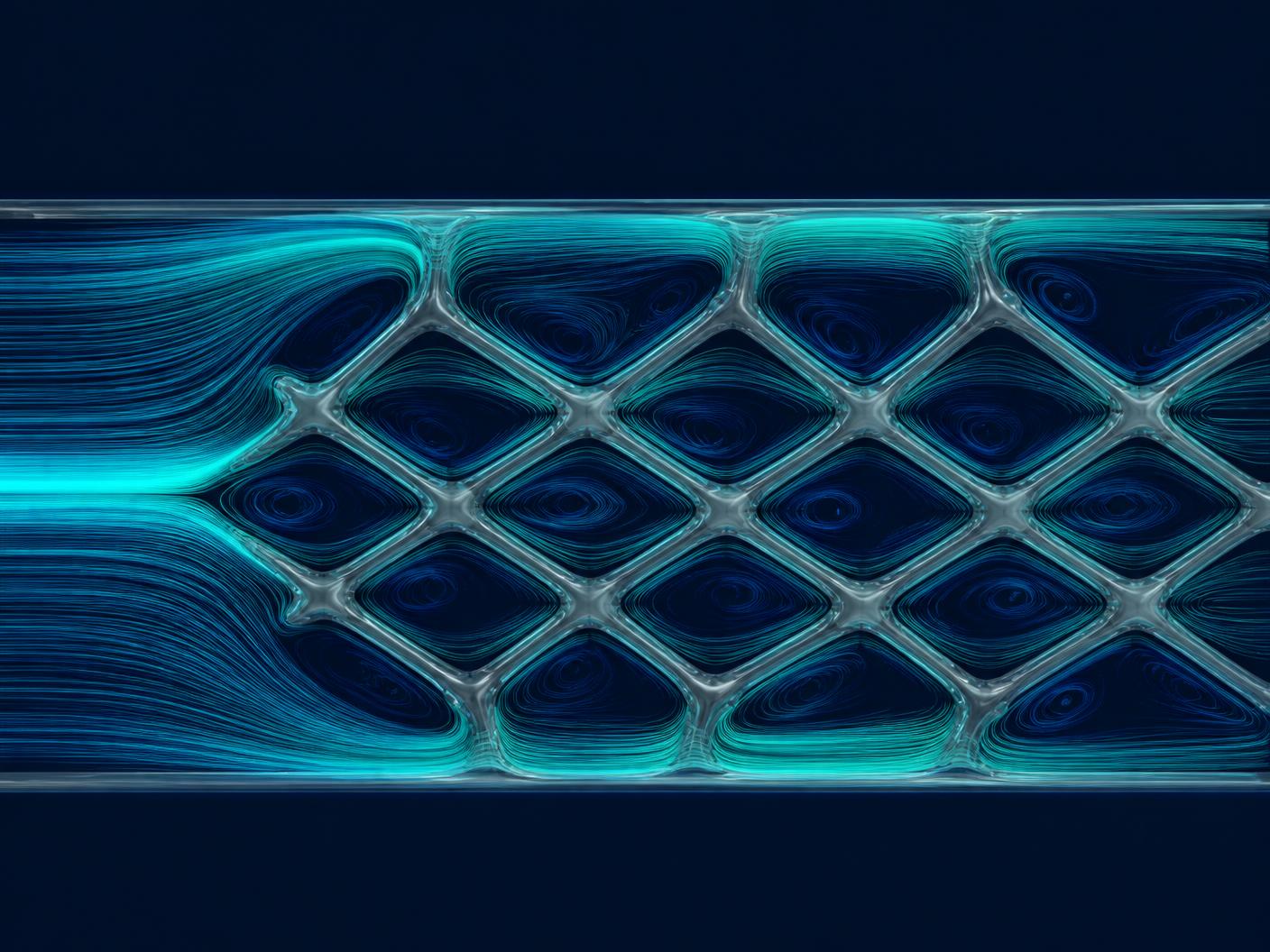
Balanced strand distribution
Balanced hydraulics
Conventional
Non-symmetric strand patterns create unequal flow resistance and uneven distribution across the channel.
SV-NanoMatrix™ HDG
A proprietary balanced strand distribution delivers an even shear profile and uniform channel flow behaviour.
Engineering benefit: Reduced localized deposition probability and a more stable ΔP trend.
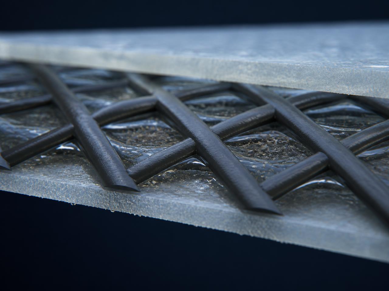
Optimized channel geometry
Shear stabilization
Conventional
Conventional non-symmetric geometries create preferential directional flow paths and stagnation pockets under load.
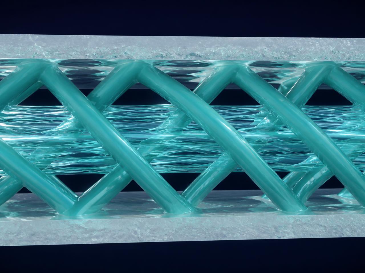
SV-NanoMatrix™ HDG
Our engineered symmetric geometry supports improved flow redistribution and better surface shear stability across the membrane area.
Engineering benefit: Enhanced anti-deposition behaviour through micro-mixing and controlled boundary-layer conditions.
Symmetric channel geometrics control the feed-channel velocity profile, limiting stagnant zones, enhancing shear conditions and stabilizing ΔP trends. SV-NanoMatrix™ integrates this symmetric open architecture to deliver stable, repeatable feed-channel hydraulics under industrial wastewater loading.
Improved cleaning recovery
- Higher permeate recovery resilience
- Reduced cleaning duration per cycle
Predictable ΔP growth trend
- Slower ΔP rise and stable plateau
- Repeatable baseline after CIP
Low permanent fouling accumulation
- Reduced irreversible deposit volume
- Cleaner channel condition across rows
Proven performance
Measurable results
- ~67%
- Lower surface roughness
- Reduces fouling initiation
- ~58%
- Lower CPI
- Longer membrane life
- 25%
- Lower pressure drop
- Enhances energy efficiency
- 2×
- Repeatable long-cycle flux
- 95% vs 55% at day 90
Thermo-FR™ reduces fouling accumulation from 1.00 to 0.45 g/m² and lifts repeatable long-cycle flux from 55% to 95% compared with standard membranes under identical wastewater RO test conditions.
Channel geometry
Standard vs HDG — Hydrodynamic Channel Geometrics, engineered to outperform
HDG — Hydrodynamic Channel Geometrics is our flagship proprietary technology built for demanding applications where performance, reliability and efficiency matter most.
Conventional channel geometry
- Restricted flow channels increase pressure drop
- Dead zones and stagnation lead to faster fouling
- Fouling is difficult to remove completely
- Lower flux and productivity over time
- Unfavorable contact angle, preferential flow paths and lower shear stability
HDG geometry (SV-NanoMatrix™)
- Symmetric open channel architecture with optimized contact angle
- Uniform flow redistribution and micro-mixing
- Minimized stagnation pockets and higher shear stability
- Lower pressure drop saves operating cost
- Stable, repeatable hydraulics under industrial loading
Manufacturing
Roll-to-roll nanoprinting precision
Layer-by-layer nanoimprint coating on a continuous web gives repeatable thickness, uniform geometry and consistent surface chemistry across every square metre of active area.
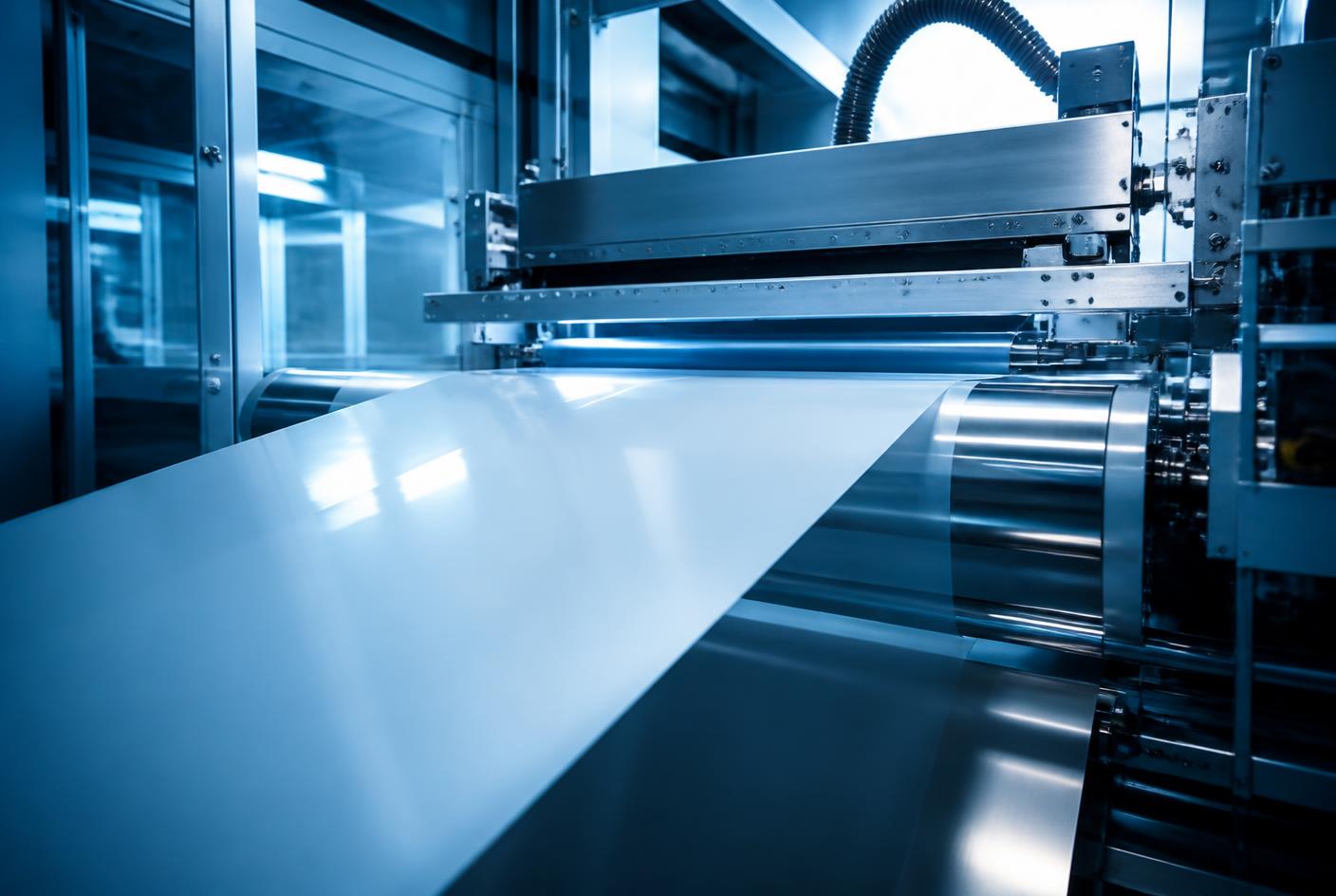
- 01
Ink reservoir & syringe pump
Metered delivery of the coating chemistry at controlled rate.
- 02
Slot-die head & meniscus
Stable meniscus forms an even wet film across full web width.
- 03
Soft wafer mold imprint
Nanoscale geometry transferred layer-by-layer onto the flexible substrate.
- 04
Water bath conditioning
Controlled thermal/aqueous conditioning stabilizes the surface layer.
- 05
Backup roller & rewinder
Consistent tension control for repeatable thickness across the roll.
Selective Layer Optimization
Polymer-science driven selective layer for superior rejection.
Thermo-FR Fouling Resistant
Engineered surface shield for excellent fouling control.
HDG Channel Geometrics
Advanced geometric flow design for low pressure drop.
Roll-to-Roll Nanoprinting
Precise and consistent layer-by-layer manufacturing.
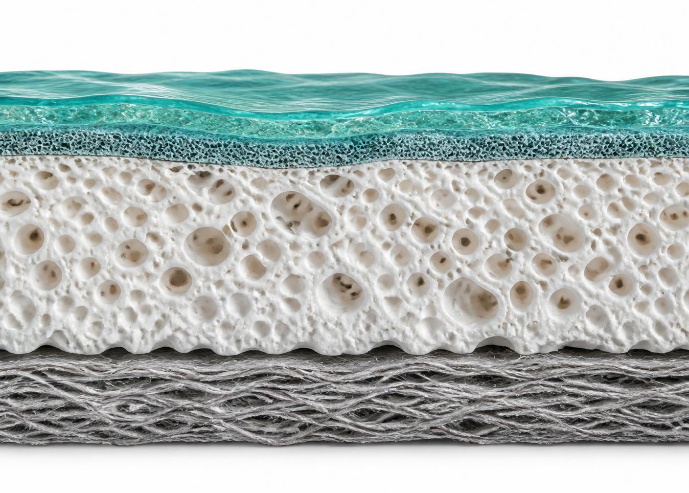
Selective layer architecture
Four engineered layers, printed and conditioned in sequence — from the ultra-thin desalination layer down to the non-woven backing that holds dimensional stability under pressure.
Selective Layer
Polymer science
Intermediate Layer
Optimized support
Porous Support Layer
High strength
Non-woven Backing
Dimensional stability
Different geometry. Different performance. Engineered to perform.
Engineered for stability, built for long-term value and designed for real-world industrial wastewater challenges.